Illustration of the positioning method of the optical elements. (dowel
4.6 (791) · € 28.00 · En Stock

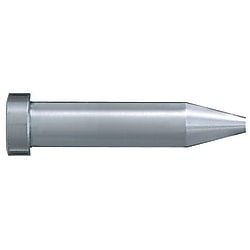
Download scientific diagram | Illustration of the positioning method of the optical elements. (dowel pins, Ø=6 mm, M6) will guide the base plate into footprint (see Fig. 2). All element base plates rest on four or more free cylindrical pillars (Ø=14 mm) which will define the vertical position of the optical elements. The alignment procedure was performed in three steps: measurements of the reference points (the footprints, see below) on the bottom plate of the inner chamber, measurements on each individual optical element after assembly and finally measurements on the elements when mounted in their final position in the chamber. For the alignment two instruments have been used. A conventional level instrument (vertical precision ~±0.05 mm) and a Platinum FaroArm (see Fig. 4). The latter is a coordinate measuring machine with a measuring range of 1.2 m and volumetric maximum deviation of ±0.018 mm. In these measurements a touch probe was used which means that data points are taken automatically when the probe touches the object. By loading the CAD drawings of objects into the FaroArm software a direct comparison between the real object and the CAD drawing can be made during the measurements. from publication: ION OPTICS ALIGNMENT IN THE ELECTROSTATIC DOUBLE STORAGE RING DESIREE | The alignment of the ion optics is always a critical task during the construction of a storage ring. In the electrostatic double ring, DESIREE a somewhat unconventional method has been chosen for the alignment process. In terms of ion optics alignment the quadrupoles are the | Alignment, Ions and Ion Optics | ResearchGate, the professional network for scientists.

Illustration of the positioning method of the optical elements. (dowel
Investigation of mechanical properties and elucidation of factors affecting wood-based structural panels under embedment stress with a circular dowel i: analysis of the influence of various conditions on the embedment properties
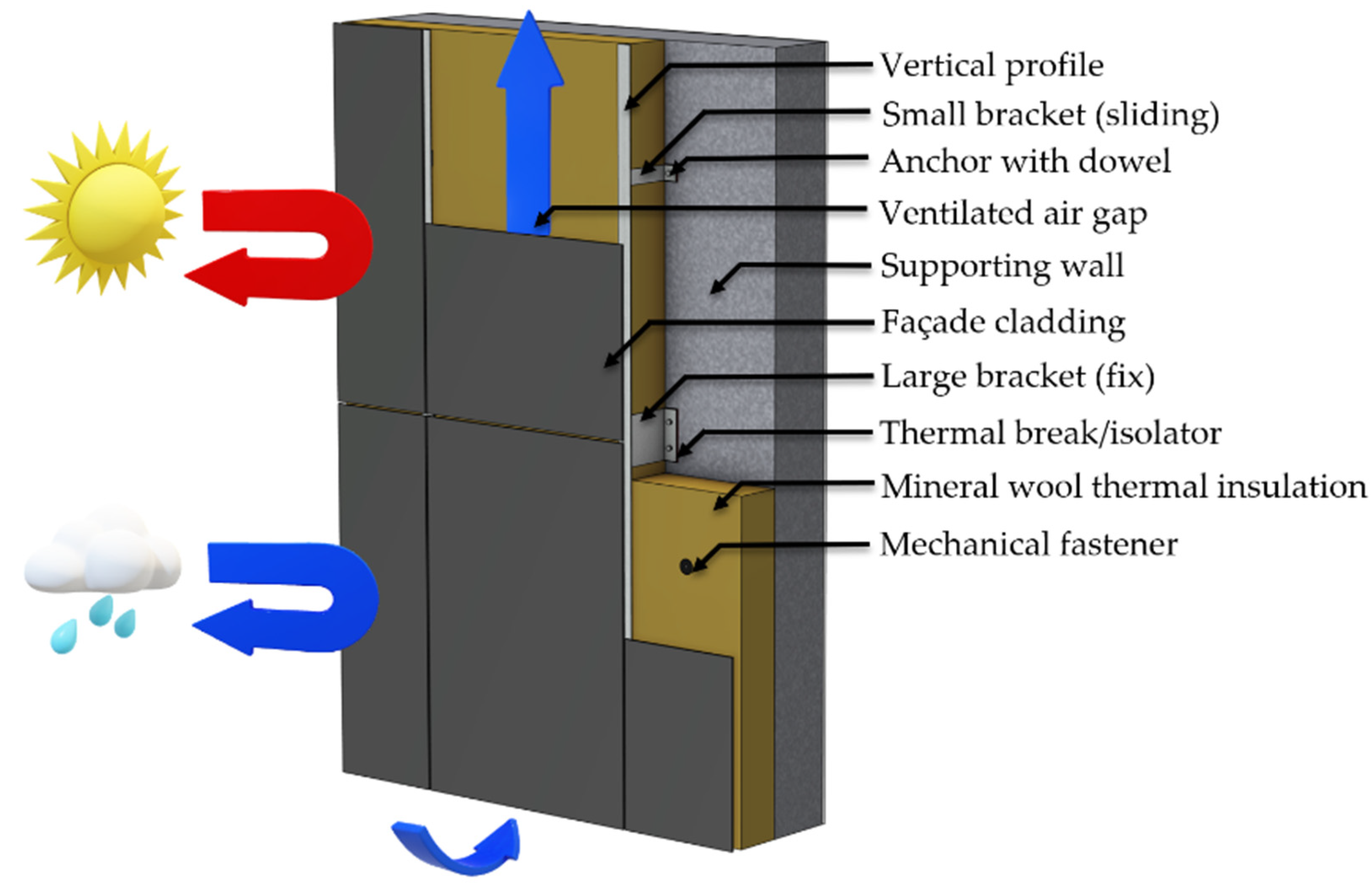
Buildings, Free Full-Text
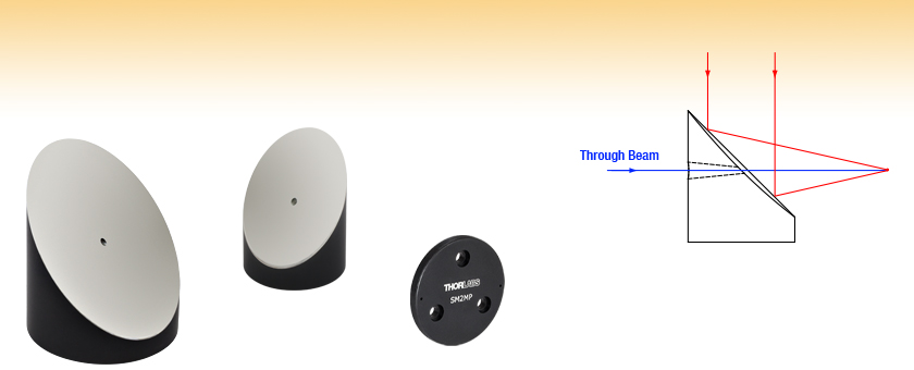
Off-Axis Parabolic Mirrors with Through Holes, Protected Silver Coating
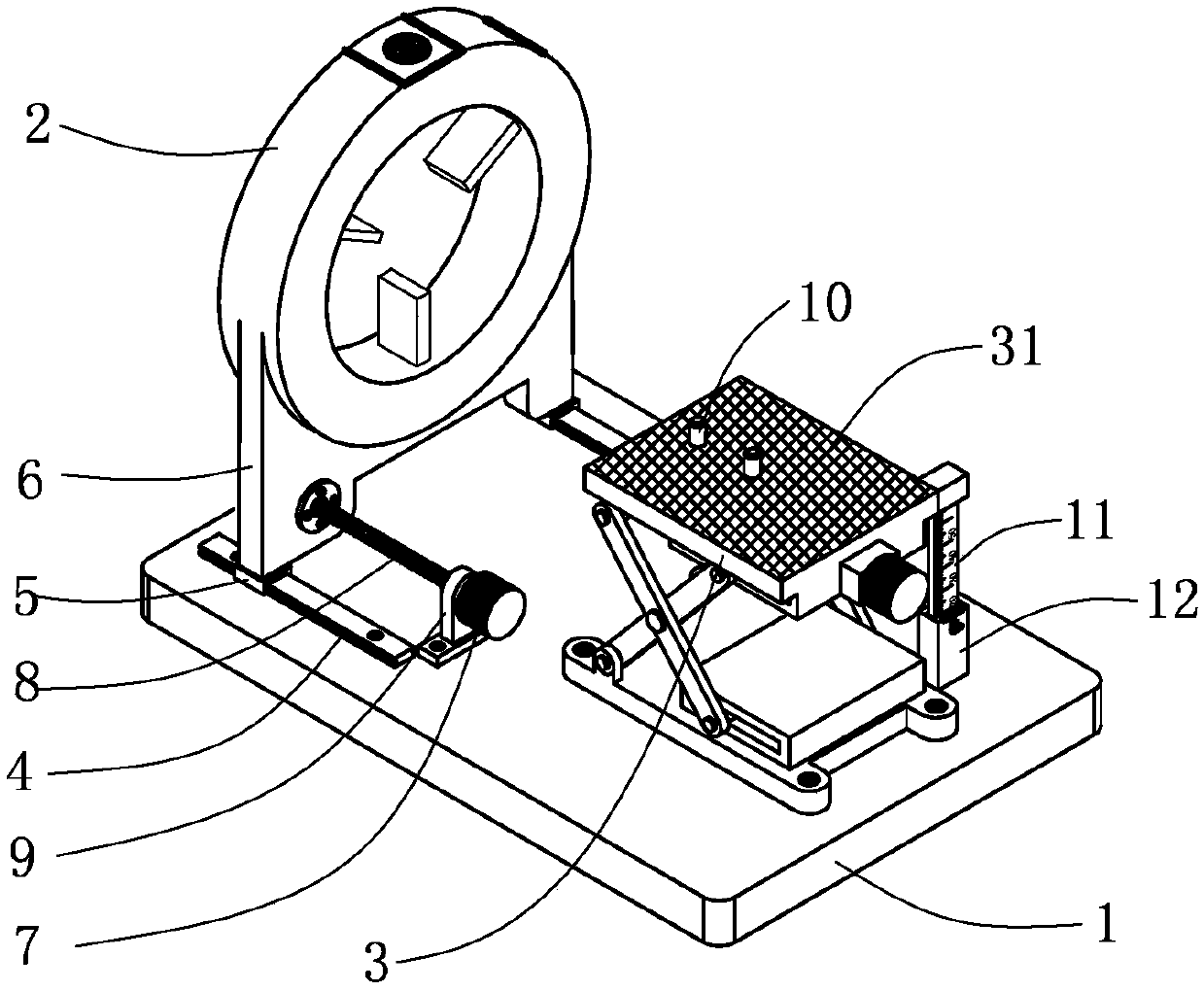
Universal platform capable of achieving butt joint of lenses and detectors of different types - Eureka
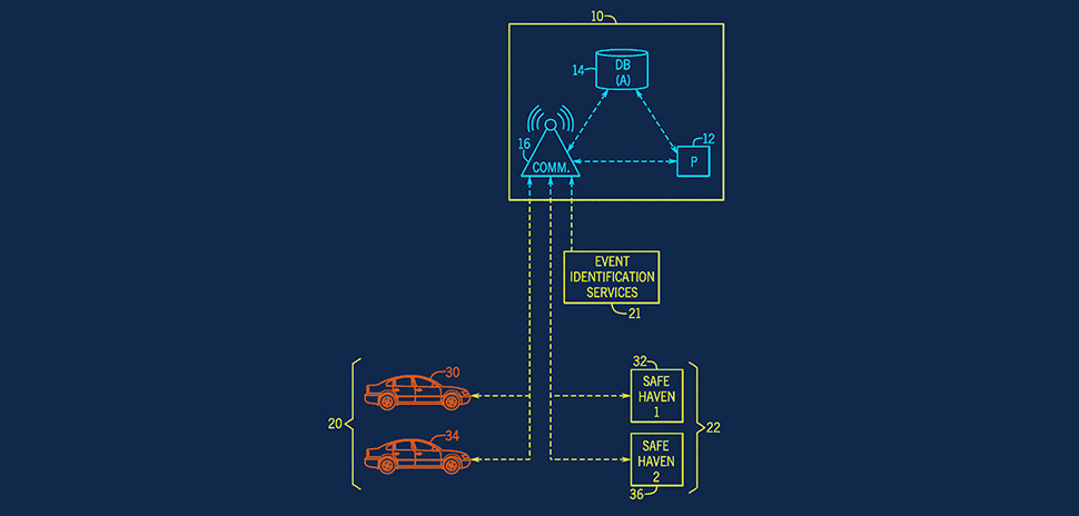
Patented: USAA's Autonomous Vehicle Haven-Seeking System and More North Texas Inventive Activity » Dallas Innovates
Structural Components and Assemblies
4 Essential Opto-mechanical Design examples

4. SETTING OUT RIGHT ANGLES AND PERPENDICULAR LINES

Binder 77-4527-4527-34704-0100 M12-D Connecting cable 2 male angled connector, Contacts: 4, shielded, moulded on the cable, IP67, Ethernet CAT5e, TPE, blue green, 2 x 2 x AWG 24, 1 m - www.
Comprehensive design analysis and verification of space-based short-wave infrared coded spectrometer via curved prism dispersion